|
Lost Tech
Archive |
Fresnel Lenses and Zone Plates
There has been much confusion over the difference between a Fresnel lens and a Fresnel zone plate. Their similar uses and similar names do not help the situation. Therefore, a quick examination of the two will help to distinguish them.
Fresnel lenses are components that take advantage of the fact that in a standard refractive lens the bulk of material (beyond an extremely small distance) does not contribute to the working of the lens. The actual bending of the light occurs at the interface between the curved surface of the lens and the space around it. A Fresnel lens is a lens where this bulk has been removed in a workable way.
If we look at Figure 1, we can follow the steps of this process. At the top is the original lens. In the center, the bulk to be removed has been shaded. Note that the edges of the material to be removed are perpendicular or parallel to the axis of the lens. This insures that the surface left does not further bend the light. Finally, in the bottom drawing, the sections that were left are dropped down on the original plane of the lens.

This example is quite simplistic. Practical Fresnel lenses have hundreds or thousands of small sawtooth sections on a relatively thin sheet. Very large lightweight lenses can be created this way that would be very impractical any other way, although, because of the sawtooth pattern, the quality of a Fresnel lens is not as good as the simple lens it was derived from.
An understanding of a Fresnel zone plate first requires some understanding of the phenomenon of diffraction. In Figure 2 on the left we see how a planar wave can be treated as a collection of many overlapping small spherical waves. This is known as Huygens principle. This collection will travel in a straight line and appear to be planar until it encounters an aperture. On exit from the aperture we can see that, although the central portion of the wave is unaffected, the masking effect of the edge of the aperture allows the small spherical wavelets at the edges to expand spherically. This appears to us as a slight bending of light around the edges of the aperture.

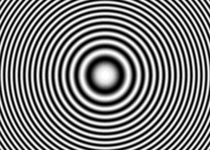
If we now look at Figure 3, we can see the derivation of a Fresnel zone plate. On the left there is a point source of light. Waves expand spherically out from this source. In the drawing, we can think of the dark sections as troughs and the white sections as peaks of the waves. If at some distance from the point source we were to examine a planar slice through the waves, we would see peaks and troughs spaced as in the center of the drawing. If we think of the dark areas as deviations from a planar wave, then if a set of apertures were constructed where the dark areas blocked light and the light areas transmitted it and allowed a planar wave to move through it, the planar wave would be broken into the sections that resembled the pattern before and the effect of diffraction on the light would result in a reconstruction of the point source. The net effect would be that the planar wave would be focused to a point by this set of apertures.

To work in all three dimensions equally, the pattern must be rotated around its center so that the apertures are aligned in all directions with the point source to be created. Otherwise the component would focus in one direction but not the other.
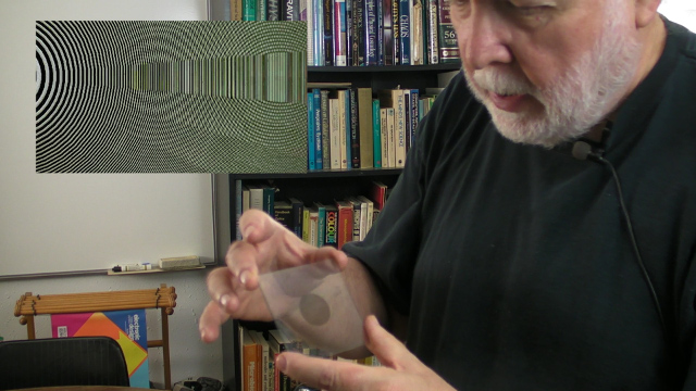
Although zone plates will act as a lens, they are very inefficient when constructed to block wave components. Instead of blocking, a zone plate can be constructed to phase shift light components dramatically increasing image quality and efficiency. By varying the density of a clear material by embossing a surface with the rings significantly increases the brightness transmitted by a component by shifting the phase of light components instead of blocking them. The same effect can be achieved by varying the refractive index of the material through careful design of metamaterials. Being essentially a planar object as opposed to large curved surfaces, practical element densities up to several hundred elements per linear inch can be manufactured using available printing and embossing processes. Holograms work by identical processes and a zone plate is literally just a hologram of a point source - a hologram of a lens, constructed properly, can be used as a lens! Comparing a transmission hologram of unbleached film where light is blocked with one produced using bleached film or embossed surfaces which shift the phase of the light demonstrates the difference in efficiancy between blocking wave components versus phase shifting them.
Derivation of the Zone Plate
 figure
4.
|
| Chromatic aberration can become
a
significant issue when using zone plates. One approach is to use of
color corrected zone plates. In this
approach, separate zone plates are designed to focus separate colors on
the same plane area. These zones plates are designed with bands acting
as
filters to SUBTRACT the wavelengths at the locations calculated and
they are superimposed on the same center such that
different wavelengths interact with different components at the same
location resulting in all colors focusing at the same plane. This would
be similar to the subtractive color processes used in modern color
transparency films. Much greater improvements in efficiancy, resolution, and color control could be achieved through the use of metamaterials by selectively controlling refractive index and wavelength interaction. (See Integral MicroOptics - A Novel Optical Computing Architecture elsewhere on this site for more on this subject and practical applications.) |
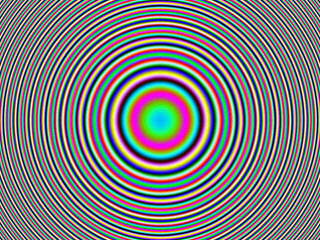 figure 6. Color Corrected Zone Plate
|
|
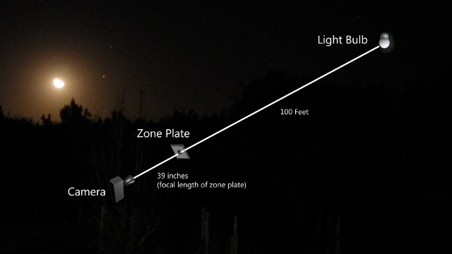
Zone
Plate
Demonstration
 figure 9. View from the camera in figure 7 as the Guckel zone plate is moved back and forth in the path of the light. |
If you are interested in further information, have questions, comments, or would like to use this material please contact the author.
You might also be interested in having a look at Integral MicroOptics - A Novel Optical Computing Architecture elsewhere on this site for continued discussion and practical applications.
copyright 1986-2018 by Ivars Vilums. All rights reserved.